Why Choose a Semi Rotary Actuator for Automation?

Time:2026-10-20 Author:Sophia
0%

Choosing a Semi Rotary Actuator can simplify automation where motion is limited, repeatable, and compact. It converts compressed air or electrical power into controlled angular movement. Typical applications include gripper rotation, valve operation, indexing tables, and material-handling fixtures.

The decision should begin with the application, not the catalogue. Engineers need to check torque, rotation angle, cycle speed, load inertia, mounting space, and environmental exposure. A unit that turns a light gripper smoothly may fail under an offset load. Small errors become expensive during continuous production.

Taiichi Ohno, a leading figure in industrial engineering, said, “Without standards, there can be no improvement.” That principle remains useful when comparing Semi Rotary Actuator options. Standard interfaces, tested cycle data, and documented maintenance requirements make performance easier to verify. They also support more reliable replacement planning.

Air-powered models often deliver fast motion and simple installation. Electric versions can provide stronger positioning control and useful energy data. Neither option is automatically better. The correct choice depends on the duty cycle, available utilities, noise limits, and control architecture.

Look closely at backlash. Check the real end-of-shaft torque. Confirm the actuator’s performance at operating pressure or voltage, not ideal conditions. A polished specification sheet can still hide practical limitations.

A Semi Rotary Actuator may reduce machine size and wiring complexity. It can also shorten installation time. Yet poor sizing creates vibration, premature wear, and unstable positioning. Careful testing remains essential. The best solution is not merely compact; it is predictable, serviceable, and suited to the machine’s actual working rhythm.
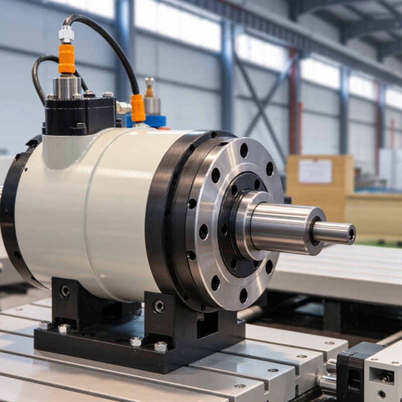
Why Choose a Semi Rotary Actuator for Automation?

Definition and Operating Principle of a Semi Rotary Actuator

A semi rotary actuator produces controlled angular movement without continuous rotation. It usually turns a shaft through a limited angle, such as 90, 180, or 270 degrees. Pneumatic models use compressed air to move a vane or rack-and-pinion mechanism. Electric versions use a motor, gearbox, and position feedback. The output torque then moves a gripper, valve, flap, or indexing table.

This design suits automation cells with repeated, defined movements. It needs less space than many linear systems. It can also simplify end-of-arm tooling. The International Federation of Robotics reported 541,302 industrial robots installed worldwide in 2023. That growth increases demand for compact motion components. However, “semi rotary” is not perfectly standardized across suppliers. Engineers should check angle range, torque, backlash, response time, and duty cycle. A small mistake here can cause vibration or incomplete positioning.

Tips: Measure the real load, not only its weight. Include friction, acceleration, and stopping impact. Select a safety margin, but avoid excessive oversizing. Large actuators may waste air or energy. Confirm the working environment, especially dust, moisture, temperature, and washdown exposure. Test the actuator with the actual tooling. Laboratory results can look better than production behavior. A clear maintenance plan also matters, although it is often treated as an afterthought.

Key Components and Motion Control Methods

Why Choose a Semi Rotary Actuator for Automation?

Key Components and Motion Control Methods

A semi rotary actuator turns compressed air into controlled angular motion, often between 90 and 180 degrees. Its compact body suits indexing tables, valve operation, grippers, and material handling tools. Core components include a cylinder housing, piston or vane, output shaft, bearings, seals, and adjustable end stops. A practical design also needs sensors for position confirmation. The shaft must match the load, torque, and required rotation angle. Undersizing creates stalled cycles and excess seal wear. It happens more often than expected.

Motion control depends on the process. Solenoid valves provide fast, repeatable switching for simple two-position movement. Flow-control valves regulate exhaust air and reduce sudden impacts. Cushioning near each stop helps protect the mechanism, especially with heavy fixtures. For intermediate positions, a proportional valve and position feedback can improve control. A PLC can coordinate actuator timing with sensors, clamps, and conveyors. Control settings should be tested at operating pressure, not only on a workbench.

Reliable operation also depends on clean, dry air and correct mounting alignment. Misalignment can add side loads to the shaft and shorten bearing life. During commissioning, measure cycle time, stopping accuracy, and housing temperature. Do not trust a calculated torque margin blindly. Friction changes as seals age, and payloads rarely behave perfectly. That is where a second sizing review earns its place.

Advantages of Semi Rotary Actuators in Automation

Why Choose a Semi Rotary Actuator for Automation?

Advantages of Semi Rotary Actuators in Automation

In automation, a semi rotary actuator turns a shaft through a defined angle. This motion suits grippers, valve controls, indexing tables, and material-handling fixtures. Unlike continuous rotary motors, it focuses energy on controlled movement between fixed positions. The result is often a compact and practical mechanism.

A major advantage is efficient torque in limited spaces. Rack-and-pinion or vane designs can deliver strong turning force without large drive assemblies. Their short movement cycles also support faster machine operations. In a packaging cell, for example, an actuator can rotate a product holder 90 degrees before the next item arrives. Pneumatic versions are especially useful where clean, repeatable motion matters.

Installation can be simple, but careful sizing remains essential. Engineers should check torque, rotation angle, load inertia, cycle frequency, and stopping requirements. A small sizing error can cause vibration, premature wear, or incomplete movement. That lesson is easy to overlook. Sensors and adjustable stops can improve positioning, while proper lubrication helps maintain service life. However, compressed air losses may reduce overall efficiency, so the power system deserves attention. Semi rotary actuators are not perfect for every task. They may be less suitable when an application needs continuous rotation, complex speed profiles, or highly precise servo control.

Why Choose a Semi Rotary Actuator for Automation? - Advantages of Semi Rotary Actuators in Automation

Typical engineering ranges are indicative only. Actual performance depends on actuator size, operating pressure, load inertia, duty cycle, mounting arrangement, and control system.
Evaluation Dimension Typical Semi Rotary Actuator Data Automation Advantage
Rotation Range Commonly 90°, 180°, or other limited preset angles Provides controlled angular movement for clamping, gripping, indexing, turning, diverting, and positioning tasks without requiring continuous rotation.
Actuation Medium Compressed air; industrial systems commonly operate around 4–8 bar Integrates easily with existing pneumatic infrastructure and supports fast, repetitive motion in factory automation.
Torque Capability Available torque varies widely by frame size; practical selection is based on load torque, friction, and a safety factor Delivers rotary force directly at the output shaft, reducing the need for separate rotary-to-angular transmission mechanisms.
Motion Speed Typically adjustable through flow controls; cycle time depends on angle, load, pressure, and cushioning Supports short-cycle operations such as part transfer, workpiece orientation, and pneumatic indexing.
End-Position Control Mechanical stops, adjustable stops, shock absorbers, or pneumatic cushioning may be used Helps limit overshoot and reduce impact at the end of travel, improving repeatability and component life.
Control Complexity Basic directional valve control; sensors can be added for position feedback Offers a relatively simple control architecture for applications that do not require fully programmable multi-axis motion.
Installation Space Compact rotary form factor with shaft or flange mounting options Fits efficiently into space-limited machine layouts and can simplify tooling or fixture integration.
Energy Behavior Uses compressed air during actuation; consumption depends on chamber volume, pressure, stroke angle, and cycle frequency Works well where a compressed-air network is already available, while air consumption should be included in operating-cost calculations.
Load Handling Requires verification of torque, radial load, axial load, inertia, and stopping requirements Proper sizing helps prevent stall, excessive vibration, premature bearing wear, and inaccurate positioning.
Environmental Suitability Can be selected for dusty, wet, or washdown environments when the enclosure and materials are appropriately rated Provides a practical option for manufacturing areas where electrical equipment may require additional protection.
Maintenance Requirements Periodic inspection of air quality, seals, fittings, cushioning, and mounting hardware Routine pneumatic maintenance can help preserve motion consistency and reduce unplanned downtime.
Best-Fit Applications Clamping, part turning, pick-and-place rotation, indexing, sorting, and fixture actuation Best suited to repetitive, defined-angle movements where simple, reliable, and economical rotary motion is preferred over continuous servo positioning.
Selection note: Choose the actuator by calculating required output torque, load inertia, angular travel, cycle time, operating pressure, stopping method, and allowable impact. Include a suitable safety margin and verify the manufacturer’s technical specifications before installation.

Common Industrial Applications and Suitable Use Cases

Why Choose a Semi Rotary Actuator for Automation?

Semi rotary actuators suit machines needing controlled angular movement rather than continuous rotation. Common travel angles include 90 and 180 degrees. Their compact bodies fit beside valves, grippers, indexing tables, and inspection fixtures. In packaging lines, they can turn cartons, position flaps, or guide products between stations. They also operate well in material handling systems where repeated, limited-angle motion saves space.

Look closely at the use case. A pneumatic actuator may suit fast cycling in clean, simple environments. An electric model may offer better control for delicate positioning and variable speeds. Valve automation is another strong application, especially for quarter-turn process valves. Semi rotary units can also support assembly tooling, welding fixtures, and small robotic joints. However, high inertia, shock loads, or frequent stops may require a different actuator. Compact does not always mean suitable.

Tips: Confirm torque at the real load, not only the catalogue rating. Check cycle frequency, stopping accuracy, air quality, temperature, and mounting space. Add a safety margin, but avoid excessive sizing. Oversized actuators may waste energy and respond poorly. Review the shaft, couplings, and end stops together. Small alignment errors can create large wear over time. In practice, the first selection is rarely perfect; testing the complete mechanism often exposes assumptions that calculations miss.

Why Choose a Semi Rotary Actuator for Automation?

Common industrial applications and suitable use cases based on typical angular positioning requirements.

Semi rotary actuators are well suited to compact, repeatable rotary movements such as clamping, gripping, indexing, diverter control, and material handling. The values show commonly used angular travel ranges; actual requirements depend on the machine design, load, speed, and stopping accuracy.

Selection Criteria, Installation, and Maintenance Considerations

Why Choose a Semi Rotary Actuator for Automation?

A semi rotary actuator suits machines that need controlled angular movement without continuous rotation. Selection begins with torque, rotation angle, speed, duty cycle, and load inertia. Add a practical safety margin, but avoid excessive oversizing. A large actuator may respond slowly and consume more energy. In field commissioning, I also check the stopping method, shaft orientation, available space, and operating temperature. The drive medium matters too. Pneumatic, electric, and hydraulic versions require different controls and maintenance routines.

Installation quality strongly affects service life. Align the actuator shaft with the driven component before tightening fasteners. Misalignment can create side loads, noise, and uneven wear. Use suitable couplings and verify that external stops do not force the actuator beyond its rated angle. Set sensors after mechanical positioning, not before. Test movement at low speed first. One common mistake is trusting a drawing more than the actual machine; real mounting surfaces are rarely perfect.

Tips: Inspect fasteners, seals, and cables during scheduled maintenance. Check for air leaks, abnormal heat, vibration, or delayed movement. Keep the working area clean, especially near exposed joints. Lubricate only when the maintenance instructions require it, because excess grease can attract dust. Record cycle counts and recurring faults. That record often reveals gradual wear earlier than a sudden failure. Review torque settings after repairs. Small changes matter.

FAQS

What does a semi rotary actuator do?

It converts compressed air into controlled angular movement. Typical rotation ranges from 90 to 180 degrees. It does not rotate continuously.

Where are semi rotary actuators commonly used?

They suit indexing tables, valve operation, grippers, and handling tools. Their compact body fits machines with limited space.

Which components are important inside the actuator?

Main parts include the housing, piston or vane, output shaft, bearings, seals, and adjustable stops. Position sensors confirm movement.

How should the actuator size be selected?

Check torque, rotation angle, speed, duty cycle, and load inertia. Include a practical safety margin. Avoid excessive oversizing. A larger unit may respond slowly.

What happens when the actuator is undersized?

It may stall during cycles and wear its seals faster. This mistake appears more often than expected. Recheck torque after real testing.

How can motion be controlled accurately?

Solenoid valves support quick two-position movement. Flow controls reduce sudden impacts. Cushioning protects the mechanism near each stop.

Can the actuator stop at intermediate positions?

A proportional valve and position feedback can improve intermediate positioning. A PLC may coordinate sensors, clamps, and conveyors. Test settings at working pressure.

What installation mistakes should be avoided?

Align the shaft before tightening fasteners. Misalignment creates side loads, noise, and uneven wear. Test movement slowly. Real mounting surfaces may differ from drawings.

How should routine maintenance be handled?

Inspect fasteners, seals, cables, leaks, heat, vibration, and delayed movement. Lubricate only when required. Excess grease can attract dust.

What should be measured during commissioning?

Measure cycle time, stopping accuracy, and housing temperature. Record cycle counts and repeated faults. Calculated torque margins are not always trustworthy.

Conclusion

A Semi Rotary Actuator is a compact motion device designed to convert pneumatic, hydraulic, or electric energy into controlled angular movement over a limited range, rather than continuous rotation. Its main components typically include a drive mechanism, housing, shaft, bearings, seals, and adjustable end stops. Motion can be managed through pressure regulation, flow control, servo positioning, sensors, or mechanical damping, depending on the required speed, torque, and accuracy. This makes the actuator suitable for repetitive and precise handling operations.

In automation, a Semi Rotary Actuator offers fast response, compact installation, reliable repeatability, and efficient operation. Common applications include robotic gripping, part positioning, indexing tables, valve operation, assembly equipment, and packaging machinery. When selecting one, engineers should evaluate torque, rotation angle, load characteristics, cycle frequency, operating environment, control method, and available space. Correct alignment, secure mounting, suitable tubing or wiring, and proper calibration are essential during installation. Regular inspection of seals, connections, lubrication, sensors, and end stops can help maintain performance, reduce downtime, and extend service life.


Sophia

Sophia

Sophia is a dedicated marketing professional with an exceptional depth of knowledge about her company's products and services. With a keen understanding of market trends and customer needs, she crafts insightful blog posts that not only inform but also engage readers, enriching the company’s online......